Understanding Capacitors
In this blog post I would like to explain the overall basics of what Capacitors are, how they work, and how they are made, as I currently understand them to be.
A CAPACITOR is a device that stores electrical energy in an Electrostatic Field. The energy is stored in such a way as to oppose any change in Voltage. Inductors oppose any change in Current, while Capacitors oppose any change in Voltage.
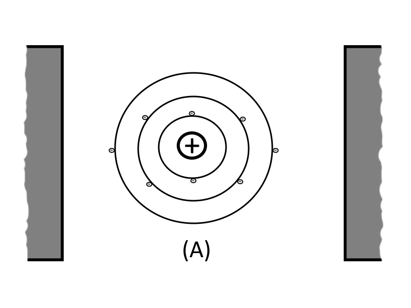
If two unlike charges are placed on opposite sides of an atom whose outermost electrons (valence electrons) cannot escape their orbits, the orbits of the electrons of the atom are distorted. A simple capacitor consists of two metal plates separated by an insulating material called a dielectric.
In the figure below, Part A shows the electrons normal orbits around an atoms proton, for an atom that is suspended between two uncharged bodies (i.e. the uncharged plates of a capacitor):
When the two uncharged bodies are charged with opposite charges (such as by being connected to a D.C. power source) and are in close proximity to each other, then an electrostatic field is produced existing between the two charged bodies. Part B shows the same orbits of an atoms electrons in the presence of charged bodies (i.e. the charged plates of a capacitor). Since the electron itself is a negative charge, the positive charged plate of the capacitor attracts the electrons via the electrostatic lines of force, pulling the electrons closer to the positive charged plate. The negative charged plate of the capacitor repels the electrons via the electrostatic lines of force, pushing them further from the negative charged plate.
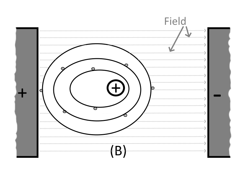
It is this ability of an electrostatic field (the electrostatic lines of force connected between the two unlike charged capacitor plates) to attract and to repel charges that allows the capacitor to store energy.
Once the D.C. power source is removed from the charged plates, the dielectric material (being an insulator) causes the electrons in the negative charged plate to not have a path for current flow to reach the positive charged plate. The distorted orbits of the atoms of the dielectric combined with the electrostatic force of attraction between the two plates hold the positive and negative charges in their original position. Thus, the energy which came from the D.C. power source is now stored in the electrostatic field of the capacitor.
The schematic symbols for a capacitor is as follows:
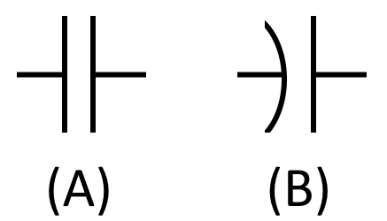
The curved plate in symbol (B) of the figure indicates that plate should be connected to a negative polarity. However if both plates are flat, as in symbol (A) of the figure, then it is OK to connect a negative polarity to either of the two plates.
The Farad
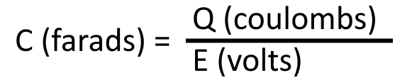
Capacitance, which is the amount of energy that can be stored by a capacitor, is measured in units called FARADS. A one-farad capacitor stores 1 coulomb (a unit of charge (Q) equal to 6.28 x 10¹⁸ electrons) of charge when a potential of 1 volt is applied across the terminal of the capacitor, and can be expressed by the formula:
The farad is a very large unit of measurement of capacitance. Therefore for convenience, the microfarad (abbreviated µF) or the picofarad (abbreviated pF) is often used. One (1.0) microfarad is equal to 0.000001 farad or 1.0 x 10⁻⁶ farad, and 1.0 picofarad is equal to 0.000000000001 farad or 1.0 x 10⁻¹² farad.
Capacitance is a physical property of the capacitor and does not depend on circuit characteristics of voltage, current, and resistance. Therefore a given capacitor always has the same value of capacitance (farads) in one circuit as it would in any other circuit in which it is connected.
Factors That Affect The Value Of Capacitance
The value of capacitance (farads) of a capacitor depends on three factors:
- Plate Area : The surface area of the plates. The plate area affects the value of capacitance in the same manner that the size of a container affects the amount of water that can be held by the container. A capacitor with the large plate area can store more charges than a capacitor with a small plate area. Therefore, the larger the plate area, the larger the capacitance.
- Distance Between Plates : Electrostatic lines of force are strongest when the charged particles that create them are close together. When the charged particles are moved further apart, the lines of force weaken, and the ability to store a charge decreases. Therefore, the closer the plates are to each other the larger the capacitance.
- Dielectric Constant : The dielectric constant of the insulating material used between the plates. The various insulating materials used as the dielectric in a capacitor differ in their ability to respond to (pass) electrostatic lines of force. A dielectric material, or insulator, is rated as to its ability to respond to electrostatic lines of force in terms of a figure called the Dielectric Constant. A dielectric material with a high dielectric constant is a better insulator than a dielectric material with a low dielectric constant. Therefore, the higher the dielectric constant the larger the capacitance.
Dielectric constants for some common materials are given as follows:
| Material | Dielectric Constant |
|---|---|
| Pure water | 81 |
| Glycerine (15° C) | 56 |
| Glass | 5 to 10 |
| Wood | 2.5 to 8 |
| Mica | 3 to 6 |
| Paraffin paper | 3.5 |
| Rubber | 2.5 to 3.5 |
| Petroleum | 2 |
| Air | 1.0006 |
| Vacuum | 1.0000 |
The Vacuum is assigned a constant of one because it is the standard of reference for which all materials are compared to. Since the dielectric constant of Air is so close to that of a Vacuum, it is common practice to simply round the value for Air to equal one.
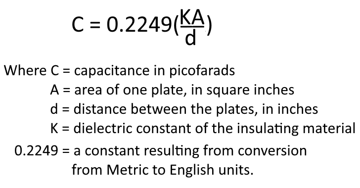
The formula used to compute the value of capacitance is:
Voltage Rating
When selecting or replacing a capacitor, consideration must be given to the value of capacitance desired, and to the amount of voltage to be applied across the capacitor. If the voltage applied across the capacitor is too great then the dielectric will break down and arcing will occur between the capacitor plates. When this happens the capacitor becomes a short-circuit and the flow of direct current through it can cause damage to other electronic parts. Each capacitor has a voltage rating (a working voltage) that should not be exceeded.
The working voltage of the capacitor is the maximum voltage that can be steadily applied to the capacitor without danger of breaking down the dielectric material of the capacitor. The working voltage depends on the type of material used as the dielectric, as well as the thickness of the dielectric. A high-voltage capacitor that has a thick dielectric must have a relatively large plate area in order to have the same capacitance as a similar low-voltage capacitor having a thin dielectric. The working voltage also depends on the applied frequency because the losses, and the resultant heating effect, increase as the frequency increases.
A capacitor with a voltage rating of 500 volts D.C. cannot be safely subjected to an alternating voltage or a pulsating direct voltage having an effective value of 500 volts. Since an alternating voltage of 500 volts (rms) has a peak value of 707 volts, a capacitor to which it is applied should have a working voltage of at least 750 volts. In practice, a capacitor should be selected so that its working voltage is at least 50% greater than the highest effective voltage to be applied to it, to not only account for peak voltage values but also for allowances for random voltage spikes that may occur as a result when other electronic components (such as resistors) fail.
Capacitor Losses
Power loss in a capacitor may be attributed to dielectric hysteresis and dielectric leakage. Dielectric hysteresis may be defined as an effect in a dielectric material similar to the hysteresis found in a magnetic material. It is the result of changes in orientation of electron orbits in the dielectric because of the rapid reversals of the polarity of the line voltage. The amount of power loss due to dielectric hysteresis depends upon the type of dielectric used. A vacuum dielectric has the smallest power loss.
Dielectric leakage occurs in a capacitor as the result of leakage current through the dielectric. Normally it is assumed that the dielectric will effectively prevent the flow of current through the capacitor. Although the resistance of the dielectric is extremely high, a minute amount of current does flow. Ordinarily this current is so small that for all practical purposes it is ignored. However, if the leakage through the dielectric is abnormally high, there will be a rapid loss of charge and an overheating of the capacitor might occur.
The power loss of a capacitor is determined by loss in the dielectric. If the loss is negligible and the capacitor returns the total charge to the circuit with no leakage, then it is considered to be a perfect capacitor with a power loss of zero.
Charging a Capacitor
For ease of explanation, the capacitor and voltage source shown in the figure below are assume to be perfect and have no internal resistance.
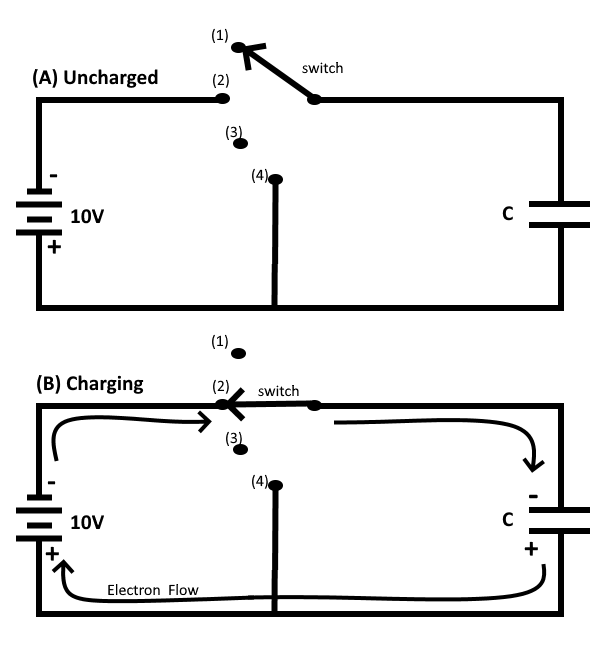
In figure (A), an uncharged capacitor is shown connected to a four-position switch. With the switch in position 1 the circuit is open and no voltage is applied to the capacitor. Initially each plate of the capacitor is a neutral body and until a difference of potential is impressed across the capacitor, no electrostatic field exists between the plates.
To CHARGE the capacitor, the switch must be thrown to position 2, which places the capacitor across the terminals of the battery (or D.C. power source). Under the assumed perfect conditions, the capacitor would reach full charge instantaneously. However the charging action is spread out over a period of time in the following discussion so that a step-by-step analysis can be made.
At the instant the switch is thrown to position 2 (figure (B) above), a displacement of electrons occurs simultaneously in all parts of the circuit. This electron displacement is directed away from the negative terminal and toward the positive terminal of the Direct Current power source (i.e. battery). A brief surge of current will flow as the capacitor charges.
At the instant the switch is closed, the positive terminal of the battery extracts an electron from the bottom conductor. The negative terminal of the battery forces an electron into the top conductor. At this same instant an electron is forced into the top plate of the capacitor and another is pulled from the bottom plate. Thus, in every part of the circuit a clockwise Displacement of electrons occurs simultaneously.
As electrons accumulate on the top plate of the capacitor and other electrons depart from the bottom plate, a difference of potential develops across the capacitor. Each electron forced onto the top plate makes that plate more negative, while each electron removed from the bottom plate causes the bottom plate to become more positive. Notice that the polarity of the voltage which builds up across the capacitor is such as to oppose the source voltage. The source voltage (emf) forces current around the circuit in a clockwise direction. The emf developed across the capacitor, however, has a tendency to force the current in a counterclockwise direction, opposing the source emf. As the capacitor continues to charge, the voltage across the capacitor rises until it is equal to the source voltage. Once the capacitor voltage equals the source voltage, the two voltages balance one another and current ceases to flow in the circuit.
In studying the charging process of a capacitor, you must be aware that NO current flows THROUGH the capacitor. The material between the plates of the capacitor must be3 an insulator. However, to an observer stationed at the source or along one of the circuit conductors, the action has all the appearances of a true flow of current, even though the insulating material between the plates of the capacitor prevents the current from having a complete path. The current which appears to flow through a capacitor is called Displacement Current.
When a capacitor is fully charged and the source voltage is equaled by the counter electromotive force (cemf) across the capacitor, the electrostatic field between the plates of the capacitor is maximum. Since the electrostatic field is maximum the energy stored in the dielectric is also maximum.
If the switch is now opened (as shown in the figure (C) below), the electrons on the upper plate are isolated. The electrons on the top plate are attracted to the charged bottom plate. Because the dielectric is an insulator, the electrons can not cross the dielectric to the bottom plate. The charges on both plates will be effectively trapped by the electrostatic field and the capacitor will remain charged indefinitely (assuming there is no leakage). You should note at this point that the insulating dielectric material in a practical capacitor is not perfect and small leakage current will flow through the dielectric. This current will eventually dissipate the charge. However, a high quality capacitor may hold its charge for a month or more before self-discharging due to leakage.
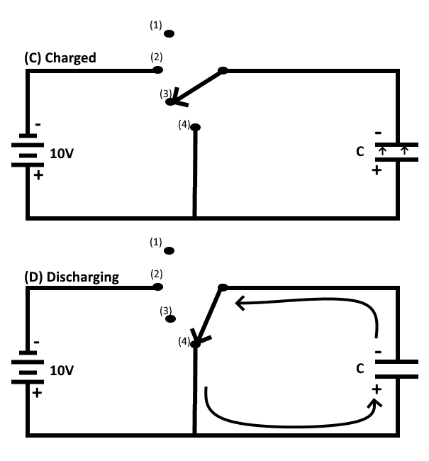
Discharging a Capacitor
To DISCHARGE the capacitor, the charges on the two plates must be neutralized. This is accomplished by providing a conducting path between the two plates (as shown in the figure (D) above). With the switch in position 4 the excess electrons on the negative plate can flow to the positive plate and neutralize its charge. When the capacitor is discharged, the distorted orbits of the electrons in the dielectric return to their normal positions and the stored energy is returned to the circuit.
It is important to note that a capacitor itself does not consume power. The energy the capacitor draws from the source is recovered when the capacitor is discharged. Power loss from a capacitor results from leakage not consumption, meaning that a capacitors stored energy is slowly leaked back into the circuit and is not consumed by the capacitor itself.
Series and Parallel
Capacitors may be connected in series or in parallel to obtain a resultant value which may be either the sum of the individual values (in parallel) or a value less than that of the smallest capacitance (in series).
The overall effect of connecting capacitors in series is the same as moving the plates of the capacitors further apart. Therefore connecting capacitors in series effectively decreases plate area and thereby decreases total capacitance.
If connecting exactly two capacitors in series then the total capacitance can be calculated with the formula : CT = (C1 * C2) / (C1 + C2)
If connecting more than two capacitors in series then the total capacitance can be calculated with the formula : CT = 1 / ( (1/C1) + (1/C2) + ... (1/Cn) )
When capacitors are connected in parallel, one plate of each capacitor is connected directly to one terminal of the source, while the other plate of each capacitor is connected to the other terminal of the source. Connecting capacitors in parallel effectively increases plate area and thereby increases total capacitance.
For capacitors connected in parallel the total capacitance is the sum of all the individual capacitances, and the total capacitance can be calculated with the formula : CT = C1 + C2 + C3 + ... Cn
Capacitor Types
A Fixed Capacitor is constructed in such a manner that it possesses a fixed value of capacitance which cannot be adjusted. Fixed capacitors are classified according to the type of material used as their dielectric, such as paper, oil, mica, ceramic, or electrolyte.
A Variable Capacitor is constructed in such manner that its value of capacitance can be varied and changed. A typical variable capacitor (adjustable capacitor) is the rotor-stator type, which consists of two sets of metal plates arranged so that the rotor plates move between the stator plates, while using air as the dielectric. As the position of the rotor is changed, the capacitance value is likewise changed. This type of capacitor is commonly used for tuning most radio receivers. Another type of variable capacitor is the trimmer capacitor, which consists of two plates separated by a sheet of mica, and uses a screw adjustment to vary the distance between the plates, thereby changing the capacitance.
Capacitor Color Codes
Although the capacitance value may be printed on the body of a capacitor, it may also be indicated by a color code. The color code used to represent capacitance values may be similar to that used to represent resistance values.
Common standards for capacitor color codes have been established by Radio Manufacturers Association (RMA), where they use one set of values to represent a six-dot color code for mica and modified paper capacitors, another set of values for six-band color code for tubular paper dielectric capacitors, another set of values for ceramic capacitors, and another set for standard mica capacitors.
However since not all capacitor manufacturers follow these RMA color code systems, then you are advised to refer to the capacitors manufacturer for that specific manufactures color code values.
Final Thoughts
Thank you for reading, I hope you found this blog post educational and helpful in some way.