Understanding Inductance
In this blog post I would like to explain the overall basics of what Inductance is, and how it is used, as I currently understand it to be.
What is Inductance?
Inductance is the characteristic of an electrical circuit and/or an electrical conductor that opposes the starting, stopping, or a change in value of current. The symbol for inductance is L and the basic unit of inductance is the HENRY (H). One henry is equal to the inductance required to induce one volt in an inductor by a change of current of one ampere per second. Inductance (the characteristic of opposing change) can be found in non-electrical applications as well. For example, anyone who has ever had to push a heavy load (wheelbarrow, car, furniture, etc...) is aware that it takes more work to start the load moving than it does to keep it moving. Once the load is moving, it is easier to keep the load moving than to stop it again. This is because the load possesses the property of inertia. Inertia is the characteristic of mass which opposes a change in velocity. Inductance has the same effect on current in an electrical circuit as inertia has on the movement of a mechanical object. It requires more energy to start, stop, or change current than it does to keep it steadily flowing.
Electromotive Force (EMF)
An electromotive force is developed whenever there is relative motion between a magnetic field and a conductor. Electromotive force is a difference of potential or voltage which exists between two points in an electrical circuit. In generators and inductors the emf is developed by the action between the magnetic field and the electrons in a conductor.
When a magnetic field moves through a stationary metallic conductor, electrons are dislodged from their orbits (valence shell orbits). The electrons move in a direction determined by the movement of the magnetic lines of flux.
The electrons move from one area of the conductor into another area. The area that the electrons moved from has fewer negative charges (electrons) and as a result it becomes positively charged (because it has less electrons than protons). The area the electrons move into becomes negatively charged (because it has more electrons than protons).
The difference between the charges in the conductor is equal to a difference of potential (or voltage). This voltage caused by the moving magnetic field is called Electromotive Force (emf). In simple terms, the action of a moving magnetic field on a conductor can be compared to the action of a broom as it sweeps a dusty floor. Consider the moving magnetic field to be a moving broom. As the magnetic broom moves along (through) the conductor, it gathers up and pushes electrons with it. The area from which electrons are moved from becomes positively charged (because that area now has less electrons than it has protons), while the area into which the electrons are moved to becomes negatively charged (because that area now has more electrons than it has protons). The potential difference between these two areas is the electromotive force or emf.
Self-Inductance
Even a perfectly straight piece of conductor has some inductance. Current in a conductor produces a magnetic field surrounding the conductor. When the current changes, the magnetic field changes. This causes relative motion between the magnetic field and the conductor, and an electromotive force (emf) is induced in the conductor. This emf is called a Self-Induced EMF because it is induced in the conductor carrying the current. The emf produced by this moving magnetic field is also referred to as Counter Electromotive Force (cemf). The polarity of the counter electromotive force is in the opposite direction to the applied voltage of the conductor. The overall effect will be to oppose a change in current magnitude.
This effect is summarized by Lenz's Law which states: The Induced EMF In Any Circuit Is Always In A Direction To Oppose The Effect That Produced It.
If the shape of the conductor wire is changed to form a loop (instead of a straight piece of wire), then the electromagnetic field around each portion of the conductor cuts across some other portion of the same conductor. Take the following figure as an example:
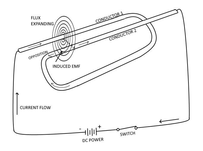 |
| Self Inductance |
In the example figure above, a length of conductor is looped so that two portions of the conductor lie next to each other. These portions are labeled conductor 1 and conductor 2. When the switch is closed, current (electron flow) in the conductor produces a magnetic field around ALL portions of the conductor. For simplicity, the magnetic field (expanding lines of flux) is shown in a single plane that is perpendicular to both conductors. Although the expanding field of flux originates at the same time in both conductors, it is considered as originating in conductor 1 and its effect on conductor 2 will be explained. With increasing current, the flux field expands outward from conductor 1, cutting across a portion of conductor 2. This results in an induced emf in conductor 2 as shown by the arrow labeled Opposing. Note that the induced emf is in the opposite direction to (in opposition to) the battery current and voltage, as stated in Lenz's law.
The direction of this induced voltage may be determined by applying the Left-Hand Rule For Generators. This rule states that if you point the thumb of your left hand in the direction of relative motion of the conductor and your index finger in the direction of the magnetic field, your middle finger (when extended) will now indicate the direction of the induced current which will generate the induced voltage (cemf), as shown in the figure above.
Once the switch has been opened, the flux field begins to collapse. Applying the left-hand rule in this case shows that the reversal of flux movement has caused a reversal in the direction of the induced voltage. The induced voltage is now in the same direction as the battery voltage. The most important thing for you to note is that the self-induced voltage opposes both changes in current. That is, when the switch is closed, this voltage delays the initial buildup of current by opposing the battery voltage, and when the switch is opened it keeps the current flowing in the same direction by aiding the battery voltage. This demonstrates that when a current is building up it produces an expanding magnetic field. This field induces an emf in the direction opposite to the actual flow of current. This induced emf opposes the growth of the current and the growth of the magnetic field. If the increasing current had not set up a magnetic field, there would have been no opposition to its growth. The whole reaction, or opposition, is caused by the creation or collapse of the magnetic field, the lines of which as they expand or contract cut across the conductor and develop the counter emf.
Since all circuits have conductors in them, then we can assume that all circuits have inductance. However, inductance has its greatest effect only when there is a CHANGE in current. Inductance does not oppose current itself, only the CHANGE in current. Where current is constantly changing as in an Alternating Current (AC) circuit, inductance has more effect because the current is constantly changing.
To increase the property of inductance, the conductor can be formed into a loop or coil. Because of this, a conductor coil is commonly called an inductor. In a coil, current through one loop produces a magnetic field that encircles the loop perpendicular to the conductor (as in figure (A) shown below). As current increases, the magnetic field expands and cuts all the loops (as in figure (B) shown below). The current in each loop affects all other loops in the coil. The field cutting the other loop has the effect of increasing the opposition to a current change.
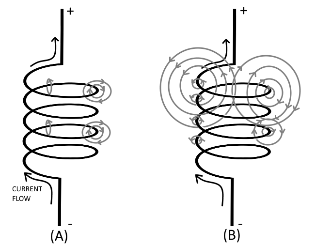 |
| Inductance |
Inductors are classified according to core type. The core is the center of the inductor, just as the core of an apple is the center of an apple. The inductor is made by forming a coil of wire around a core. The core material is normally one of two basic types: soft-iron or air. The air-core inductor may be nothing more than a coil of wire, but it is usually a coil formed around a hollow form of some nonmagnetic material such as cardboard. This nonmagnetic material serves no purpose other than to hold the shape of the coil.
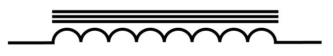 | Schematic symbol for Iron-Core Inductor. | |
 | Schematic symbol for Air-Core Inductor. |
Factors Affecting Coil Inductance
Inductance depends entirely upon the physical construction of the circuit, and can only be measured with special laboratory instruments. There are several physical factors which affect the inductance of a coil. They include:
- The number of turns in the coil : Doubling the number of turns in the coil will produce a field twice as strong, if the same current is used. A field twice as strong, cutting twice the number of turns, will induce four times the voltage. Therefore, it can be said that the inductance varies as the square of the number of turns.
- The diameter of the coil : Physically, it requires more wire to construct a coil of large diameter than one of small diameter with an equal number of turns. Therefore, more lines of force exist to induce a counter emf (cemf) in the coil with the larger diameter. Actually, the inductance of a coil increases directly as the cross-sectional area of the core increases. The formula for the area of a circle is A = πr2, therefore doubling the radius of a coil increases the inductance by a factor of four.
- The coil length : A coil that is rather widely spaced making a relatively long coil has few flux linkages, due to the greater distance between each turn. As a result, that coil has a relatively low inductance. However a coil that has closely spaced turns, making a relatively short coil, increases the flux linkage, and therefore increasing the inductance of the coil. Doubling the length of a coil while keeping the same number of turns halves the value of inductance.
- The type of material used in the core : The magnetic core (the soft iron) of an iron-core inductor is a better path for magnetic lines of force than is the nonmagnetic core of an air-core inductor. The soft-iron magnetic core's high permeability has less reluctance to the magnetic flux, resulting in more magnetic lines of force. This increase in the magnetic lines of force increases the number of lines of force cutting each loop of coil, thus increasing the inductance of the coil. It should now be apparent that the inductance of a coil increases directly as the permeability of the core material increases.
- And the number of layers of winding in the coils : The more layers of turns the inductor has, the more effectively the magnetic flux links are and therefore the flux linkage is increased. The increased number of layers (cross-sectional area) improves flux linkage. The inductance of the coil increases with each layer added.
Inductance is dependent upon the degree of linkage between the wire conductor(s) and the electromagnetic field. In a straight length of conductor, there is very little flux linkage between one part of the conductor and another. Therefore, its inductance is extremely small. Conductors become much more inductive when they are wound into coils, because there is maximum flux linkage between the conductor turns, which lie side by side in the coil.
An inductor has an inductance of 1 henry if an emf of 1 volt is induced in the inductor when the current through the inductor is changing at the rate of 1 ampere per second. The relationship between the induced voltage, the inductance, and the rate of change of current with respect to time is stated mathematically as:
| Eind = L ( ΔI / Δt ) | where Eind is the induced emf in volts, L is the inductance in henrys, and ΔI is the change in current in amperes occurring in Δt seconds. The symbol Δ (Greek letter Delta) means "a change in" |
Growth And Decay Of Current In An Inductance Circuit
When a battery is connected across a pure inductance, the current builds up to its final value at a rate determined by the battery voltage and the internal resistance of the battery. The current buildup is gradual because of the counter emf generated by the self-inductance of the inductors coil. When the current starts to flow, the magnetic lines of force move outward from the inductors coil. These lines cut the turns of wire on the inductor and build up a counter emf that opposes the emf of the battery. This opposition causes a delay in the time it takes the current to build up to a steady value. When the battery is disconnected, the lines of force collapse. Again these lines cut the turns of the inductor and build up an emf that tends to prolong the flow of current.
Electrical inductance is like mechanical inertia, and the growth of current in the inductive circuit can be likened to the acceleration of a boat that is stopped on the surface of the water, for example. The boat does not move at the instant a constant force is applied to it, but rather at the instant all the applied force is used to overcome the inertia of the boat. Once the inertia is overcome the boat will start to move. After a while, the speed of the boat reaches its maximum value and the applied force is used up in overcoming the friction of the water against the hull of the boat. When the force applied to the boat is removed, the boat still continues to move through the water for a while, eventually coming to a stop. This is because energy was being stored in the inertia of the moving boat. After a period of time the friction of the water overcomes the inertia of the boat, and the boat stops moving.
Just as inertia of the boat stored energy, the magnetic field of an inductor stores energy. Because of this, even when the power source is removed, the stored energy of the magnetic field of the inductor tends to keep current flowing in the circuit until the magnetic field collapses.
L/R Time Constant
The L/R Time Constant is a valuable tool for use in determining the time required for current in an inductor to reach a specific value.
One L/R time constant is the time required for the current in an inductor to increase to 63.2 percent of the maximum current. Each time constant is equal to the time required for the current to increase by 63.2 percent of the difference in value between the current flowing in the inductor and the maximum current.
Maximum current flows in the inductor after five L/R time constants are completed.
When an LR circuit is deenergized, the circuit current decreases (decays) to zero in five time constants at the same rate that it previously increased. Current increases and decays at the same rate in five time constants.
The value of the time constant in seconds is equal to the inductance in henrys divided by the circuit resistance in ohms. The formula used to calculate one L/R time constant is:
| Time Constant (TC) in seconds = L (in henrys) / R (in ohms) |
Power Loss In An Inductor
Since an inductor (coil) consists of a number of turns of wire, and since all wire has some resistance, every inductor has a certain amount of resistance. Normally this resistance is small. It is usually neglected in solving various types of A.C. circuit problems because the reactance of the inductor (the opposition to alternating current) is so much greater than the resistance that the resistance has a negligible effect on the current.
However, since some inductors are designed to carry relatively large amounts of current, considerable power can be dissipated in the inductor even though the amount of resistance in the inductor is small. This power is wasted power and is called Copper Loss. The copper loss of an inductor can be calculated by multiplying the square of the current in the inductor by the resistance of the winding (I2R).
In addition to copper loss, an iron-core coil (inductor) has two iron losses:
- Hysteresis Loss : due to power that is consumed in reversing the magnetic field of the inductor core each time the direction of current in the inductor changes.
- Eddy-Current Loss : due to heating of the core by circulating currents that are induced in the iron core by the magnetic field around the turns of the coil, and circulate within the iron core only.
All these losses dissipate power in the form of heat. Since this power cannot be returned to the electrical circuit, it is lost power.
Mutual Inductance
Whenever two coils are located so that the flux from one coil links with the turns of the other coil, a change in flux in one coil causes an emf to be induced in the other coil. This allows the energy from one coil to be transferred or coupled to the other coil. The two coils are said to be coupled or linked by the property of Mutual Inductance (M).
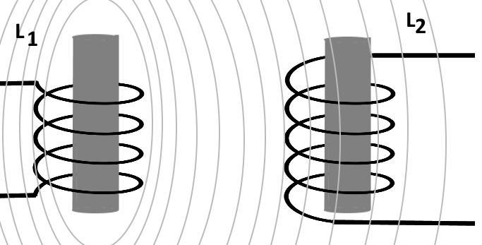 |
| Mutual Inductance |
The amount of mutual inductance depends on the relative position of the two coils. If the coils are separated a considerable distance, the amount of flux common to both coils is small and the mutual inductance is low. Conversely, if the coils are close together so that nearly all the flux of one coil links the turns of the other, the mutual inductance is high.
The mutual inductance between two coils can be increased greatly by mounting the coils on a common iron core.
But keep in mind that since this is inductance (the opposition to a change in current), then once the current in one coil reaches a steady value, the induced current in the other coil returns to zero. The current is only induced from one coil to the other while the current value is changing (either increasing or decreasing), and not while it is steady.
Good examples of electrical components that rely entirely upon the properties of mutual inductance are step-up and step-down Transformers.
Factors Affecting Mutual Inductance
The mutual inductance of two adjacent coils is dependent upon:
- The physical dimensions of the two coils,
- The number of turns in each coil,
- The distance between the two coils,
- The relative positions of the axes of the two coils,
- And the permeability of the cores.
The coefficient of coupling between two coils is equal to the ratio of the flux cutting one coil to the flux originated in the other coil. If the two coils are so positioned with respect to each other so that all of the flux of one coil cuts all of the turns of the other coil, the coils are said to have a unity coefficient of coupling. It is never exactly equal to unity (1), but it approaches this value in certain types of coupling devices. If all of the flux produced by one coil cuts only half the turns of the other coil, the coefficient of coupling is 0.5. The coefficient of coupling is designated by the letter K.
The mutual inductance between two coils, L1 and L2, is expressed in terms of the inductance of each coil and the coefficient of coupling K, and it can be expressed in a formula as:
M = K * Sqrt(L1 * L2)
where:
- M = Mutual inductance in henrys,
- K = Coefficient of coupling,
- L1 and L2 = Inductance of coil in henrys.
Series Inductors Without Magnetic Coupling
When inductors are well shielded or are located far enough apart from one another, the effect of mutual inductance is negligible. If there is no mutual inductance (magnetic coupling) and the inductors are connected in series, the total inductance is equal to the sum of the individual inductances. As a formula:
LT = L1 + L2 + L3 + ... Ln
where:
- LT is the total inductance,
- L1, L2, L3, are the inductances of L1, L2, and L3,
- Ln means that any number (n) of inductors may be used.
The inductances of inductors in series are added together like the resistances of resistors in series.
Series Inductors With Magnetic Coupling
When two inductors in series are so arranged that the filed of one links the other, the combined inductance is determined as follows:
LT = L1 + L2 ± 2M
where:
- LT = The total inductance,
- L1, L2 = The inductances L1, L2,
- M = The mutual inductances between the two inductors
The plus sign is used with M with the magnetic fields of the two inductors are aiding each other. The minus sign is used with M when the magnetic field of the two inductors oppose each other. The factor 2M accounts for the influences of L1 on L2 and L2 on L1.
Parallel Inductors Without Coupling
The total inductance (LT) of inductors in parallel is calculated in the same manner that the total resistance of resistors in parallel is calculated, provided the coefficient of coupling between the coils is zero. As a formula:
(1/LT) = (1/L1) + (1/L2) + (1/L3) + ... (1/Ln)
Final Thoughts
Thank you for reading, I hope you found this blog post educational and helpful in some way.