Understanding Alternating Current (AC) : Part 1
In this blog post I would like to explain the overall basics of what Alternating Current (AC) is, and how it is made and used, as I currently understand it to be.
Current that regularly changes direction is called Alternating Current (AC). Alternating current is current which constantly changes in amplitude (value), and which reverses direction at regular intervals (polarity of value). Direct current flows in one direction only, while alternating current is constantly changing in amplitude (value) and direction (polarity).
With direct current (DC), current flows only in one direction (from the negative terminal, through the circuit, to the positive terminal), and the amplitude of current is determined by the number of electrons flowing past a point in a circuit in one second. If, for example, a coulomb of electrons moves past a point in a wire in one second and all of the electrons are moving in the same direction, the amplitude of direct current in the wire is one ampere (in this example).
Similarly, with alternating current (AC), if half a coulomb of electrons moves in one direction past a point in the wire in half a second, then reverses direction and moves past the same point in the opposite direction during the next half-second, a total of one coulomb of electrons passes the point in one second, making the amplitude of the alternating current one ampere (in this example).
Disadvantages of DC compared to AC
When commercial use of electricity became wide-spread and used in residential homes, certain disadvantages in using direct current in the home became apparent. If a commercial direct current system is used, the voltage must be generated at the level (amplitude or value) required by the load. To properly light a 240-volt lamp, for example, the DC generator at the power station must generate and deliver 240 volts to every resident. If a 120-volt lamp is to be supplied power from the 240-volt generator, then a resistor or another 120-volt lamp must be placed in series with the 120-volt lamp to drop the extra 120 volts. When the resistor is used to reduce the voltage from 240 volts to 120 volts, an amount of power equal to that consumed by the 120-volt lamp is wasted, which therefore makes providing DC power to residential houses impractical and inefficient.
Another disadvantage in using direct current in the residential home, is that the high ampere current (I) of direct current (DC) from the generating power station must be transmitted a long distant over wires (power lines) from the power station to the consumer. When this happens, a large amount of power is lost due to the resistance(R) of the wire combined with that high ampere value. The power loss is equal to I2R. However, this loss can be greatly reduced if the power is transmitted over the lines at a very high voltage level and a low current level. This is not a practical solution to the power loss in the DC system since the load would then have to be operated at a dangerously high voltage. Because of the disadvantages related to transmitting and using direct current, practically all modern commercial electric power companies generate and distribute alternating current (AC) instead of direct current (DC).
Since power in a DC system must be transmitted at low voltage and high current levels, the I2R power loss becomes a problem in the DC system. Since power in an AC system can be transmitted at a high voltage level and a low current level, the I2R power loss in the AC system is much less than that in the DC system.
Unlike direct voltages and direct current, alternating voltages and alternating current can be stepped up or stepped down in amplitude by a device called a Transformer. Use of the transformer permits efficient transmission of electrical power over long-distance lines by stepping the alternating voltage up, which simultaneously steps the alternating current down. At the electrical power station, the transformers output power is at high voltage and low current levels, and is then transmitted across the power lines from the power station to the consumer with minimal power loss (as compared to the amount of power that would have been lost if it had instead been a direct current transmission of low voltage and high current). At the consumer end of the transmission lines, the voltage is stepped down (and the current is stepped up) by the use of a transformer to the lower voltage values required by the load. Due to its inherent advantages and versatility, alternating current has replaced direct current in all but a few commercial power distribution systems.
The waveform of voltage or current is a graphical picture of changes in voltage or current values over a period of time.
ElectroMagnetism
In a previous blog post I had discussed the fundamental theories concerning simple magnets and magnetism, but how magnetism can be used to produce electricity was only briefly mentioned. ELECTROMAGNETIM is the term used for the general subject area that explains how magnetism is affected by an electric current and how electricity is affected by magnetism.
Some generalized points to know regarding the relationship between magnetism and electricity are:
- An electric current always produces some form of magnetism.
- The most commonly used means for producing or using electricity involves magnetism.
- The peculiar behavior of electricity under certain conditions is caused by magnetic influences.
Magnetic Fields
If a compass is placed in the vicinity of a current-carrying conductor, the compass needle will align itself at right angles to the conductor, thus indicating the presence of a magnetic force. The presence of this magnetic force can be demonstrated by running a vertical conductor through the center of a horizontal piece of cardboard and then running an electric current through the conductor. The direction of the magnetic force produced by the current can then be determined by placing a compass at various points on the cardboard next to the conductor and noting the compass needle direction. The direction of the magnetic force is assumed to be the direction in which the north pole of the compass points.
The relation between the direction of the magnetic lines of force around a conductor and the direction of electron current flow in the conductor may be determined by means of the Left-Hand Rule For A Conductor: if you grasp the conductor in your left hand with the thumb extended in the direction of the electron flow (current)(negative to positive), your fingers will point in the direction of the magnetic lines of force. If you applied this rule to the above cardboard compass example, you will see that your fingers will point in the direction that the north pole of the compass points when it is placed in the magnetic field surrounding the conductor wire. On electrical graphs and diagrams, an arrow symbol is usually drawn to show the direction of current in a length of wire.
This is important to know because whenever two (or more) adjacent parallel conductors are carrying current in the same direction, the magnetic lines of force combine and increase the strength of the field around the conductors. Two parallel conductors carrying currents in opposite directions will oppose each other in the space between the wires, thus deforming the field around each conductor. This means that if two parallel and adjacent conductors are carrying current in the same direction the fields about the two conductors aid each other, and if two parallel and adjacent conductors are carrying current in the opposite direction the fields about the conductors repel each other.
The magnetic field around a current-carrying wire exists at all points along the wire. When a straight wire is wound around a core, it forms a coil, and the magnetic field about the core will assume a different shape. When current is passed through the coil, the magnetic field about each turn of wire links with the fields of the adjacent turns. The combined influence of all the turns produces a two-pole field similar to that of a simple bar magnet. One end of the coil is a north pole and the other end is a south pole.
The direction of the magnetic field around a straight wire depends on the direction of current in that wire. Thus, a reversal of current in a wire causes a reversal in the direction of the magnetic field that is produced. It stands to reason then that a reversal of the current in a coil also causes a reversal of the two-pole magnetic field about the coil.
When the direction of the current in a coil is known, the magnetic polarity of the coil can be determined by using the Left-Hand Rule For Coils: grasp the coil in your left hand, with your fingers wrapped around in the direction of the electron current flow. Your thumb will then point toward the north pole of the coil.
The strength or intensity of a coil's magnetic field depends on a number of factors, some of which are:
- The number of tuns of wire in the coil.
- The amount of current flowing in the coil.
- The ratio of the coil length to the coil width.
- The type of material in the core.
When current flows in a conductor, the atoms in the conductor all line up in a definite direction, which collectively produces a magnetic field. When the direction of the current changes, the direction of the atom's alignment also changes, causing the magnetic field to change direction. to reverse all the atoms requires that power be expended, and this power is lost. This loss of power (in the form of heat) is called Hysteresis Loss, and is common in all AC equipment. However, this loss is usually only a problem for things like motors, generators, and transformers.
Basic AC Generation
A current-carrying conductor produces a magnetic field around itself. A changing magnetic field produces an emf in a conductor. If a conductor is placed in a magnetic field, and either the field or the conductor moves, an emf is induced in the conductor. This effect is called electromagnetic induction.
The easiest and fastest method to generate alternating current is to simply rotate a loop of conductive wire as it is suspended between the north pole of one permanent magnet and the south pole of another permanent magnet, while the two permanent magnets are in close proximity to each other.
The following image shows a suspended loop of wire being rotated in a clockwise direction through the magnetic field between the poles of a permanent magnet. For ease of explanation, the loop has been divided into a dark half and light half. Notice in (A) of the figure that the dark half is moving along (parallel to) the magnetic lines of force. Consequently, it is cutting NO lines of force and is instead just traveling with it. The same is true of the light half, which is moving in the opposite direction. Since the conductors are cutting no lines of force, no emf is induced.
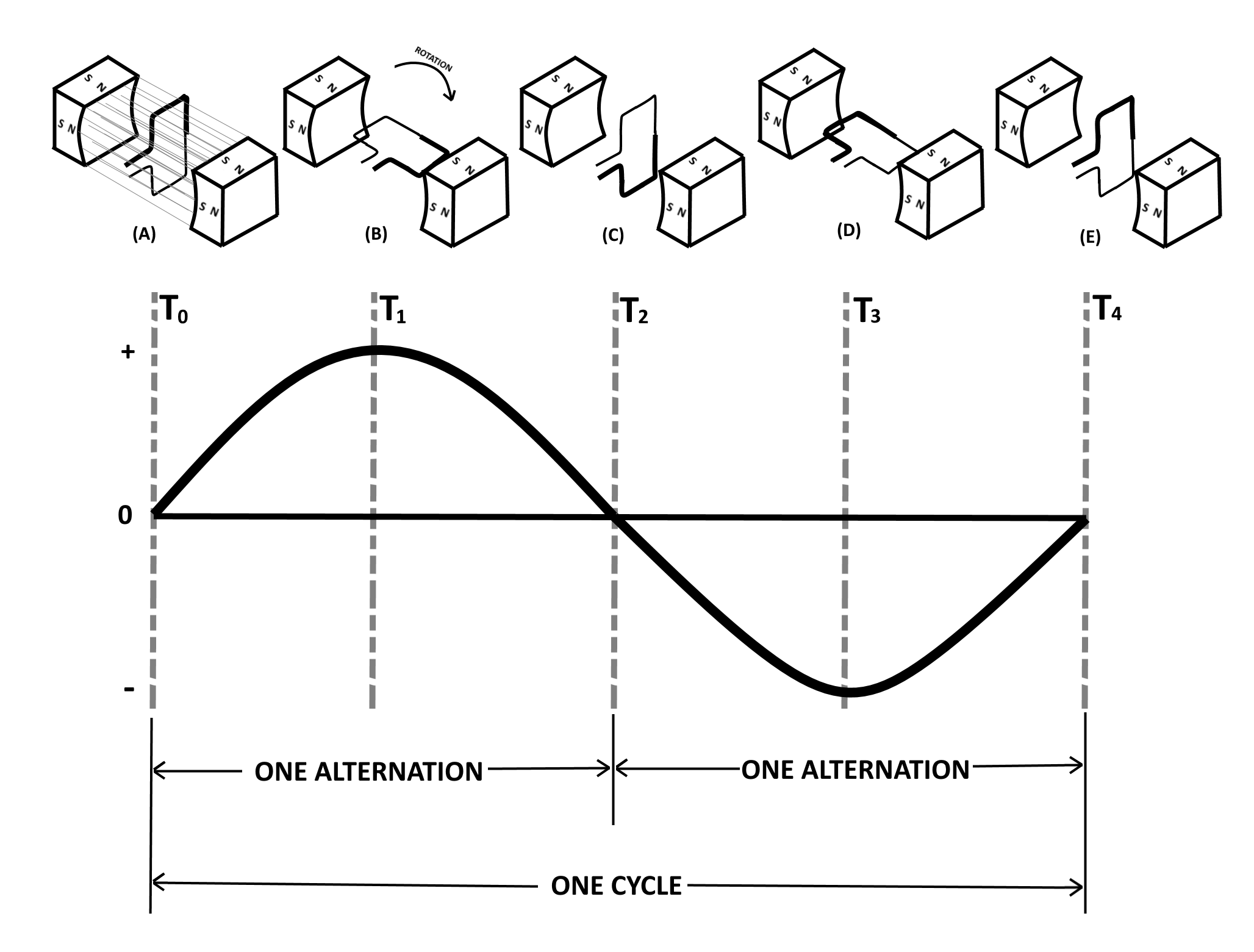
As the loop rotates toward the position shown in (B), the conductive wire of the loop cuts more and more lines of force per second (inducing an ever-increasing voltage) because it is cutting more directly across the magnetic field (magnetic lines of force) instead of just traveling along with it. At (B), the conductor is shown completing one-quarter of a complete revolution, or 90°, of a complete circle. Because the conductor is now cutting directly across the field, the voltage induced in the conductor is maximum. When the value of induced voltage at various points during the rotation from (A) to (B) is plotted on a graph (and the points connected via a line), a curve appears as shown above.
As the loop continues to be rotated toward the position shown in (C), it now starts to cut fewer and fewer lines of force. The induced voltage decreases from its peak value. Eventually, the loop is once again moving in a plane parallel to the magnetic field, and no emf is induced in the conductor. The loop has now been rotated through half a circle (one alternation, or 180°). If the preceding quarter-cycle is plotted, it appears as shown above.
When the same procedure is applied to the second half of rotation (180° through 360°), the curve appears as shown above. Notice the only difference is in the polarity of the induced voltage. Where previously the polarity was positive, it is now negative.
The sine curve shows the value of induced voltage at each instance of time during rotation of the loop. Notice that this curve contains 360°, or two alternations. TWO ALTERNATIONS represents ONE complete CYCLE of rotation.
Assuming a closed path is provided across the ends of the conductor loop, you can determine the direction of current in the loop by using the Left-Hand Rule For Generators. The left-hand rule is applied as follows: First, place your left hand on the illustration (shown below) with the fingers as shown. Your Thumb will now point in the direction of rotation (relative movement of the wire to the magnetic field); your Forefinger will point in the direction of magnetic flux (north to south); and your Middle Finger will point in the direction of electron current flow.
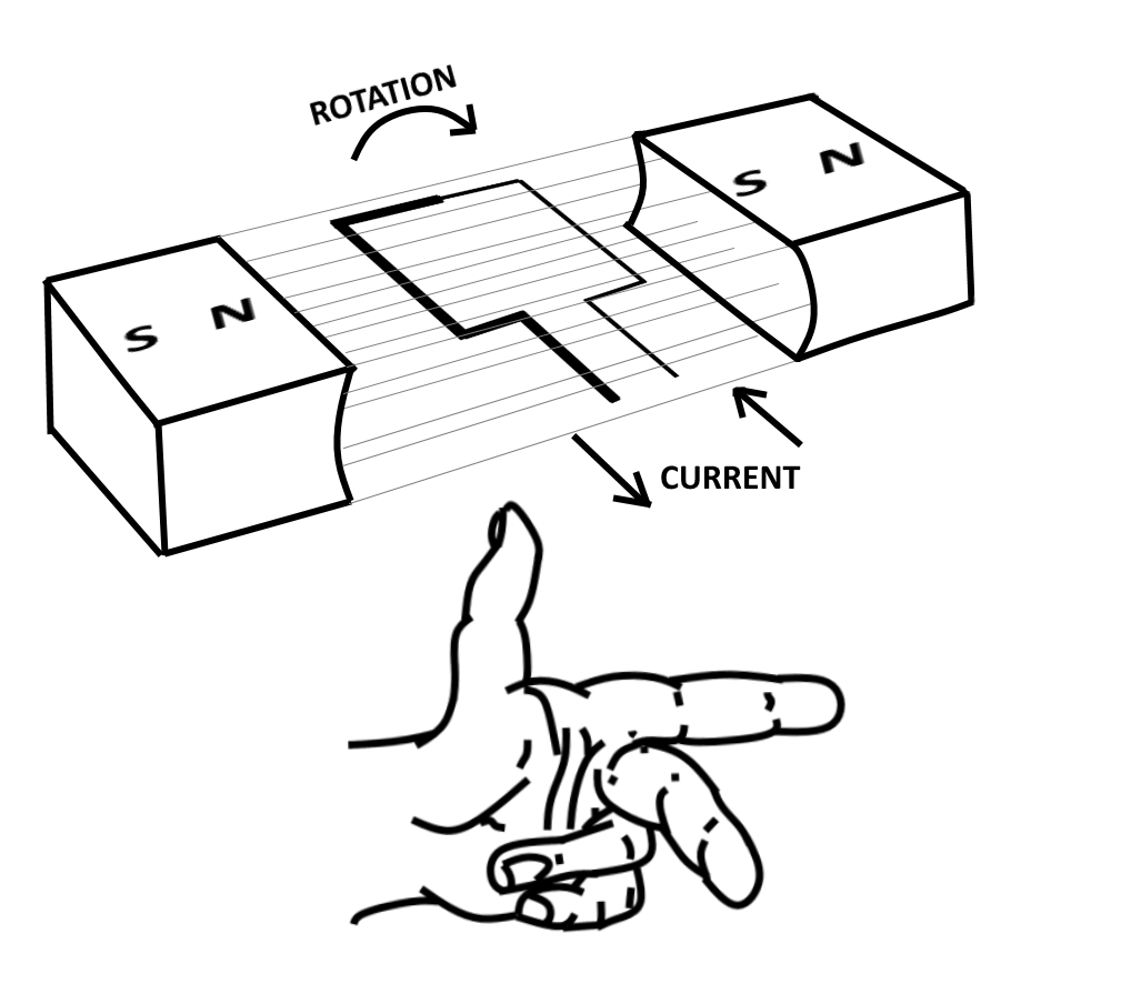
By applying the left-hand rule to the dark half of the loop in (B) in the first figure above, you will find that the current flows in the direction indicated by the heavy arrow. Similarly, by using the left-hand rule on the light half of the loop, you will find that current therein flows in the opposite direction. The two induced voltages in the loop add together to form one total emf. It is this emf which causes the current in the loop.
When the loop rotates to the position shown in (D) of the figure, the action reverses. The dark half is moving up instead of down, and the light half is moving down instead of up. By applying the left-hand rule once again, you will see that the total induced emf and its resulting current have reversed direction. The voltage builds up to maximum in this new direction, as shown by the sine curve, shown above. The loop finally returns to its original position (E), at which point voltage is again zero. The sine curve represents one complete cycle of voltage generated by the rotating loop. All the illustrations used in this topic show the wire loop moving in a clockwise direction. In actual practice, the loop can be moved clockwise or counterclockwise. Regardless of the direction of movement, the left-hand rule applies.
If the loop is rotated through 360° at a steady rate, and if the strength of the magnetic field is uniform, the voltage produced is a sine wave of voltage (shown above). Continuous rotation of the loop will produce a series of sine-wave voltage cycles, or in other words, an AC voltage.
Continue with Alternating Current - Part 2