Understanding Direct Current (DC) : Part 2
Continued from Direct Current - Part 1...
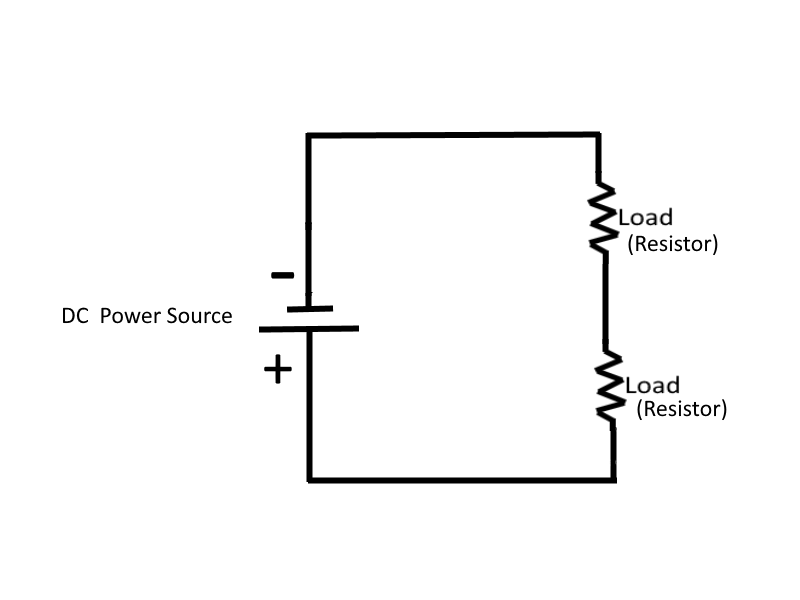
Series DC Circuits
When two unequal charges are connected by a conductor, a complete pathway for current exists. An electric circuit is a complete conducting pathway. It consists not only of the conductor, but also includes the path through the voltage source. Inside the voltage source, the current flows from the positive terminal through the source itself and then emerges at the negative terminal. Outside the voltage source, the current flows from the voltage sources negative terminal, through the circuit, and then to the connected voltage sources positive terminal.
A Series Circuit is defined as a circuit that contains only one path for current flow.
 |
Resistance in a Series Circuit
In a series circuit, the total circuit resistance (RT) is equal to the sum of the individual resistances.
Therefore, for a series circuit:
| RT = R1 + R2 + R3 + ... Rn | where the subscript n denotes any number of additional resistances that might be in the equation |
For example, if we have a circuit that contains three 10 ohm resistors, then the total resistance RT equals R1 + R2 + R3, or RT = 10 + 10 + 10, which equates to RT = 30 ohms in this example.
In some circuit applications, the total resistance is known and the value of one of the circuit resistors has to be determined. The equation RT = R1 + R2 + R3 can be transposed to solve for the value of the unknown resistance. For example, if the total resistance of a circuit containing three resistors is 40 ohms, and two of the circuit resistors are 10 ohms each, then calculating the value of the third resistor (RT) is as easy as subtracting the R1 and R2 from both sides of the equation, so that R3 equals RT - R1 - R2, or R3 = 40 - 10 - 10, which equates to R3 = 20 ohms in this example.
Current in a Series Circuit
Since there is only one path for current to flow in a series circuit, the same amount of current must flow through each component of the circuit. Therefore to determine the amount of current in a series circuit, only the amount of current that flows through one of the components need to be known. This can easily be verified by placing a ampere meter into the circuit at various points and seeing that each meter would indicate the same value of current.
Voltage in a Series Circuit
In a circuit that consists of a single resistor and a voltage source, the voltage dropped across the resistor is the total voltage across the circuit and is equal to the applied voltage. However, in a circuit that consists of multiple resistors and a voltage source, the total voltage across the series circuit is also equal to the applied voltage but it consists of the sum of the individual resistor voltage drops. In any series circuit, the SUM of the resistor voltage drops must equal the source voltage.
Therefore, for a series circuit:
| ET = E1 + E2 + E3 + ... En | where the subscript n denotes any number of additional voltage that might be in the equation |
NOTE: When you use Ohm's Law, the quantities for the equation MUST be taken from the SAME part of the circuit. For example, the voltage across R2 is computed using the current through R2 and the resistance of R2.
The value of the voltage dropped by a resistor is determined by the applied voltage and is in proportion to the circuit resistances. The voltage drops that occur in a series circuit are in direct proportion to the resistances. This is the result of having the same current flow through each resistor - the larger the ohmic value of the resistor, the larger the voltage drop across it.
Power in a Series Circuit
Each of the resistors in a series circuit consumes power which is dissipated in the form of heat. Since this power must come from the source, the total power must be equal to the power consumed by the circuit resistances.
In a series circuit the total power is equal to the sum of the power dissipated by the individual resistors. Total power (PT) is equal to:
| PT = P1 + P2 + P3 + ... Pn | where the subscript n denotes any number of additional power dissipated that might be in the equation |
For example, if we have a series circuit that consists of three resistors having values of 5 ohms, 10 ohms, and 15 ohms, to find the total power when 120 volts is applied to the circuit, we first find the total resistance, and then calculate the circuit current by dividing the applied voltage by the total resistance amount, then calculate the power dissipated at each resistor, and sum those power dissipated values to obtain the total power.
Given:
| R1 = 5 ohms | |
| R2 = 10 ohms | |
| R3 = 15 ohms | |
| E = 120 volts |
Solution: The total resistance is found first:
| RT = R1 + R2 + R3 | |
| RT = 5 ohms + 10 ohms + 15 ohms | |
| RT = 30 ohms |
By using the total resistance and the applied voltage, the circuit current is calculated:
| I = (ET) / (RT) | |
| I = 120 volts / 30 ohms | |
| I = 4 amps |
By means of the power formulas, the power can be calculated for each resistor:
For R1:
| P1 = I2 * R1 | |
| P1 = (4 amps)2 * 5 ohms | |
| P1 = 80 watts |
For R2:
| P2 = I2 * R2 | |
| P2 = (4 amps)2 * 10 ohms | |
| P2 = 160 watts |
For R3:
| P3 = I2 * R3 | |
| P3 = (4 amps)2 * 15 ohms | |
| P3 = 240 watts |
To obtain total power:
| PT = P1 + P2 + P3 | |
| PT = 80 watts + 160 watts + 240 watts | |
| PT = 480 watts |
To check the answer, the total power delivered by the source can be calculated:
| Psource = Isource * Esource | |
| Psource = 4 amps * 120 volts | |
| Psource = 480 watts |
The total power is equal to the sum of the power used by the individual resistors.
Rules For Series DC Circuits
- The same current flows through each part of a series circuit.
- The total resistance of a series circuit is equal to the sum of the individual resistances.
- The total voltage across a series circuit is equal to the sum of the individual voltage drops.
- The voltage drop across a resistor in a series circuit is proportional to the ohmic value of the resistor.
- The total power in a series circuit is equal to the sum of the individual powers used by each circuit component.
An important fact to keep in mind when applying Ohm's Law to a series circuit is to consider whether the values used are component values or total values. When the information available enables the use of Ohm's Law to find total resistance, total voltage, and total current, total values must be inserted into the formula.
| To find total resistance: | RT = ET / IT | ||
| To find total voltage: | ET = IT * RT | ||
| To find total current: | IT = ET / RT |
Note: IT is equal to I in a series circuit. However, the distinction between IT and I in the formula should be noted. The reason for this is that other circuits may have several currents, and it will be necessary to differentiate between IT and other currents.
To compute any quality (E, I, R, or P) associated with a single given resistor, the values used in the formula must be obtained from that particular resistor. For example, to find the value of an unknown resistance, the voltage across and the current through that particular resistor must be used.
| To find the value of a resistor: | R = ER / IR | ||
| To find the voltage drop across a resistor: | ER = IR * R | ||
| To find current through a resistor: | IR = ER / R |
Kirchhoff's Voltage Law
Kirchhoff's law states: "The algebraic sum of the voltage drops in any closed path in a circuit and the electromotive forces in the path is equal to zero."
Stated another way, the voltage drops and voltage sources in a circuit are equal at any given moment in time. If the voltage sources are assumed to have one sign (positive or negative) at that instant and the voltage drops are assumed to have the opposite sign, the result of adding the voltage sources and voltage drops will be zero.
In applying Kirchhoff's law to direct current circuits, the terms electromotive force and emf apply to voltage sources such as batteries or power supplies.
When Kirchhoff's law is properly applied, an equation can be set up for a closed loop and the unknown circuit value can be calculated, which otherwise would not be possible to calculate using Ohm's law alone.
Kirchhoff's voltage law can be written as an equation:
| Ea + Eb + Ec + ... En = 0 | where Ea, Eb, etc.. are the voltage drops or emf's around any closed circuit loop, and where the subscript n denotes any number of additional voltage drops that might be in the equation |
To set up the equation for an actual circuit, the following procedure is used:
- Assume a direction of current through the circuit (the correct direction is desirable but not necessary).
- Using the assumed direction of current, assign polarities to all resistors through which the current flows.
- Place the correct polarities on any sources included in the circuit.
- Starting at any point in the circuit, trace around the circuit, writing down the amount and polarity of the voltage across each component in succession. The polarity used is the sign AFTER the assumed current has passed through the component. Stop when the point at which the trace was started is reached.
- Place these voltages, with their polarities, into the equation and solve for the desired quantity.
In many applications a circuit may contain more than one source of emf. Sources of emf that cause current to flow in the same direction are considered to be Series Aiding and the voltages are added. Sources of emf that would tend to force current in opposite directions are said to be Series Opposing and the effective source voltage is the difference between the opposing voltages. When two opposing sources are inserted into a circuit, current flow would be in a direction that is determined by the larger source.
Circuit Terms and Characteristics
A Reference Point is an arbitrarily chosen point to which all other points in the circuit are compared. In series circuits, any point can be chosen as a reference and the electrical potential at all other points can be determined in reference to that point.
The reference point of a circuit is always considered to be at zero potential. Since the Earth (ground) is said to be at a zero potential, the term Ground is used to denote a common electrical point of zero potential. The schematic symbol for ground is :
In most electrical equipment, the metal chassis is the common ground the the many electrical circuits. When each electrical circuit is completed, common points of a circuit at zero potential are connected directly to the metal chassis, thereby eliminating the need for a large amount of connecting wire. The electrons pass through the metal chassis (a conductor) to reach other points of the circuit.
Most voltage measurements used to check proper circuit operation in electrical equipment are taken in respect to ground. One meter lead is attached to a grounded point and the other meter lead is moved to various test points on the circuits.
A circuit is said to be Open when a break exists in a complete conducting pathway. Although an open occurs when a switch is used to deenergize a circuit, an open may also develop accidentally (such as when a fuse is blown). To restore a circuit to proper operation, the open must be located, its cause determined, and repairs made.
An open circuit has Infinite resistance. Infinity represents a quantity so large it cannot be measured. The symbol for infinity is :
A Short Circuit is an accidental path of low resistance which passes an abnormally high amount of current. A short circuit exists whenever the resistance of a circuit or the resistance of a part of a circuit drops in value to almost zero ohms. A short often occurs as a result of improper wiring or broken insulation.
It should be noted that voltage sources have some amount of resistance also. If a meter is connected across the terminals of a good 1.5 volt battery then it reads about 1.5 volts. When the same battery is inserted into a complete circuit, the meter reading decreases to something less than 1.5 volts. This difference in terminal voltage is caused by the Internal Resistance of the batter due to the opposition to current offered by the electrolyte in the battery. All sources of electromotive force (emf) have some form of internal resistance which causes a drop in terminal voltage as current flows through the source.
Maximum power is transferred from the source to the load when the resistance of the load is equal to the internal resistance of the source. The efficiency of power transfer (ratio of output power to input power) from the source to the load increases as the load resistance is increased. The efficiency approaches 100% as the load resistance approaches a relatively large value compared with that of the source, since less power is lost in the source. The efficiency of power transfer is only 50% at the maximum power transfer point (when the load resistance equals the internal resistance of the source). The efficiency of power transfer approaches zero efficiency when the load resistance is relatively small compared with the internal resistance of the source.
If efficiency is important and the amounts of power involved are large, then the load resistance should be made large relative to the source resistance so that the losses are kept small. But where the problem of matching a source to a load is important, as in most communications circuits, a strong signal may be more important than a high percentage of efficiency, and therefore the efficiency of power transfer should be only about 50%, however the power transfer would be the maximum that the source is capable of supplying.
Continue with Direct Current - Part 3