Understanding Direct Current (DC) : Part 3
Continued from Direct Current - Part 2...
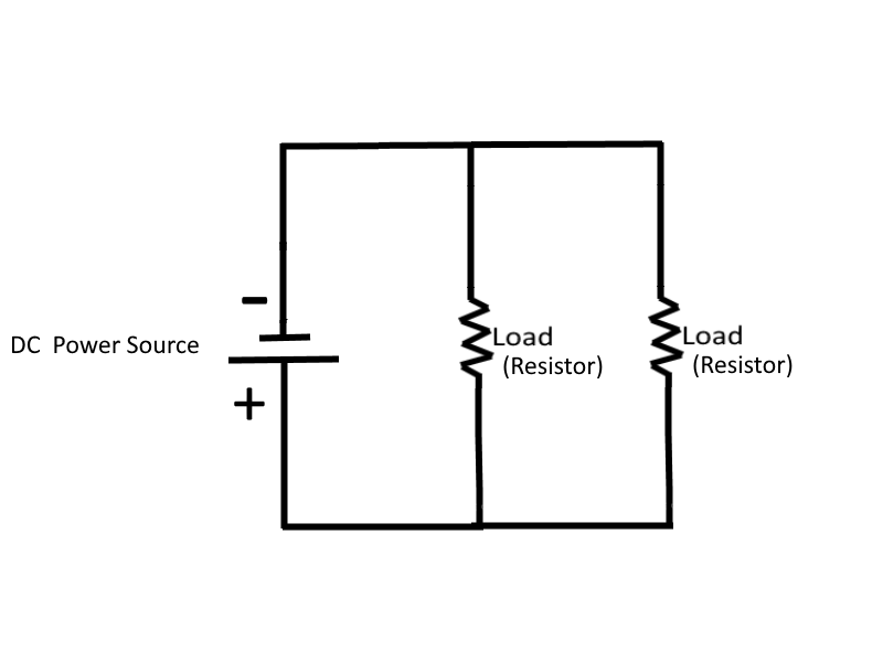
Parallel DC Circuits
A Parallel Circuit is defined as a circuit having more than one current path connected to a common voltage source. Therefore parallel circuits must contain at least two or more resistances which are not connected in series.
In a parallel circuit, the same voltage is present in each branch (a branch is a section of a circuit that has a complete path for current).
| The voltage is equal to the applied voltage (Es), and expressed in equation form as: | Es = ER1 = ER2 |
 |
Ohm's law states that the current in a circuit is inversely proportional to the circuit resistance. This fact is true in both series and parallel circuits. There is a single path for current in a series circuit, and the amount of current is determined by the total resistance of the circuit and the applied voltage. In a parallel circuit the source current divides among the available paths.
The division of current in a parallel network follows a definite pattern. This pattern is described by Kirchhoff's Current Law, which states "The algebraic sum of the currents entering and leaving an junction of conductors is equal to zero".
Kirchhoff's current law can be written as an equation:
| Ia + Ib + Ic + ... In = 0 | where Ia, Ib, etc.. are the current entering and leaving the junction, and where the subscript n denotes any number of additional current that might be in the equation |
Unlike series circuits, in parallel circuits (when using Kirchhoff's current law) the currents ENTERING the junction are considered to be POSITIVE and currents LEAVING the junction are considered to be NEGATIVE. Therefore, when solving a problem using Kirchhoff's current law, the currents must be placed into the equation with the proper polarity signs attached.
In parallel circuits, the total resistance (RT) of the circuit can be calculated by using the values of total voltage (ET) and total current (IT), using the formula: RT = ET / IT.
Since the total resistance of a parallel circuit is smaller than any of the individual resistors, total resistance of a parallel circuit is not the sum of the individual resistor values as was the case in a series circuit. The total resistance of resistors in parallel is also referred to as Equivalent Resistance (Req). The terms total resistance and equivalent resistance are used interchangeably.
There are several methods used to determine the equivalent resistance of parallel circuits. The best method for a given circuit depends on the number and value of the resistors. For a circuit where all resistors have the same value, the following simple equation is used: Req = R / N, where R is the ohmic value of one resistor and N is the number of resistors. This equation is valid for any number of parallel resistors of EQUAL VALUE.
An important point to remember is that the equivalent resistance of a parallel circuit is always less than the resistance of any branch. Therefore, to solve for equivalent resistance for a circuit that has a number of unequal parallel resistors, use the following reciprocal method: Req = 1 / ( (1/R1) + (1/R2) + ... (1/Rn) )
Product Over The Sum Method: A convenient method for finding the equivalent, or total, resistance of two parallel resistors is by using the following formula: Req = (R1 * R2) / (R1 + R2)
Power computations in a parallel circuit are essentially the same as those used for the series circuit. Since power dissipation in resistors consists of a heat loss, power dissipations are additive regardless of how the resistors are connected in the circuit. The total power is equal to the sum of the power dissipated by the individual resistors. Like the series circuit, the total power consumed by the parallel circuit is PT = P1 + P2 + P3 + ... Pn
Rules for Parallel DC Circuits
- The same voltage exists across each branch of a parallel circuit and is equal to the source voltage.
- The current through a branch of a parallel network is inversely proportional to the amount of resistance of the branch.
- The total current of a parallel circuit is equal to the sum of the individual branch currents of the circuit.
- The total resistance of a parallel circuit is found by the general formula: (1/Req) = (1/R1) + (1/R2) + (1/R3) + ... (1/Rn), or one of the formulas derived from this general formula.
- The total power consumed in a parallel circuit is equal to the sum of the power consumptions of the individual resistances.
Problems involving the determination of resistance, voltage, current, and power in a parallel circuit are solved as simply as in a series circuit. The procedure is the same:
- Draw the circuit diagram,
- State the values given and the values to be found,
- Select the equations to be used in solving for the unknown quantities based on the known quantities,
- And substitute the known values in the equation you have selected and solve for the unknown value.
Equivalent Circuits
It is often necessary to reduce a complex circuit (a complex circuit is a circuit consisting of both series and parallel circuits) into a simpler form. Any complex circuit consisting of resistances can be redrawn (reduced) to a basic equivalent circuit containing the voltage source and a single resistor representing total resistance. This process is called reduction to an Equivalent Circuit.
Once the equivalent resistance is known, a new circuit can be drawn consisting of a single resistor (to represent the equivalent resistance) and the voltage source. By breaking down a complex circuit into equivalent circuits, troubleshooting individual branches of a complex circuit becomes much more simplified.
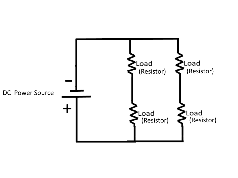
Series-Parallel DC Circuits (Complex Circuits)
A circuit consisting of both series and parallel elements is referred to as a combination circuit, or a complex circuit. Solving for the quantities and elements in a combination circuit is simply a matter of applying the laws and rules already discussed above, while using the equivalent circuit method. To simplify a complex circuit to a simple circuit containing only one load, equivalent circuits are substituted (on paper) for the complex circuit they represent.
 |
The major difference between an open in a parallel circuit and an open in a series circuit is that in the parallel circuit, depending upon where the open is, the open would not necessarily disable the circuit. If the open condition occurs in a series portion of the circuit, there will be no current because there is no complete path for current flow. If, on the other hand, the open occurs in a parallel path, some current will still flow in the circuit. The parallel branch where the open occurs will be effectively disabled, total resistance of the circuit will increase and total current will decrease.
A short circuit in a parallel network has an effect similar to a short in a series circuit. In general, the short will cause an increase in current and the possibility of component damage regardless of the type of circuit involved.
Opens and shorts alike, if occurring in a circuit, result in an overall change in the equivalent resistance. This can cause undesirable effects in other parts of the circuit due to the corresponding change in the total current flow. A short usually causes components to fail in a circuit which is not properly fused or otherwise protected. The failure may take the form of a burned-out resistor, damaged source, or a fire in the circuit components and wiring.
Fuses and other circuit protection devices are (or should be) installed in equipment circuits to prevent damage caused by increases in current. These circuit protection devices are designed to open if current increases to a predetermined value. Circuit protection devices are (or should be) connected in series with the circuit or portion of the circuit that the device is protecting, so that when the circuit protection device opens then the current flow ceases in the circuit and acts as a switch to disengage power to the circuit.
Voltage Dividers
Most electrical and electronics equipment use voltages of various levels throughout their circuity. One circuit within a single piece of equipment may require a 6 volt supply, another circuit within that same piece of equipment a 12 volt supply, and still another a 24 volt supply. These voltage requirements could be supplied by three individual power sources, however that would be very impractical, expensive, and require a considerable amount of additional physical space. The most common method of supplying these voltages is to use a single voltage source and a Voltage Divider.
100 volts is 100 volts, regardless of its polarity (positive or negative), when referenced to ground. Voltage polarities are considered as being positive or negative in respect to a reference point, usually ground.
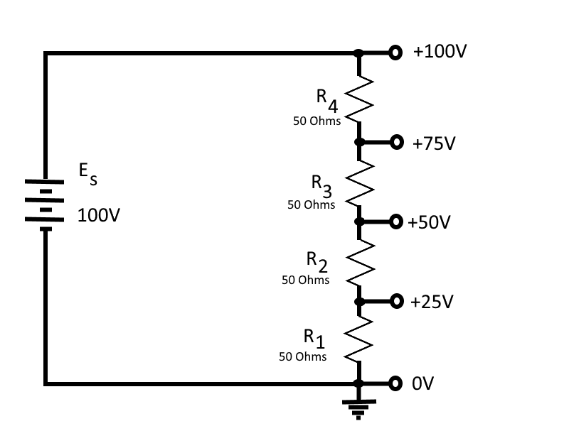
The simplest way to make a voltage divider is to create a series circuit that contains resistors of desired ohmic values for a given power source, so that each resistor causes a specific voltage drop to occur as a result of its resistive properties in a series circuit.
For example, if we have a series circuit connected to a 100 volt power source, and the series circuit consists of four 50 ohms resistors, then each resistor develops (drops) 25 volts. If we place a reference point before and after each resistor to act as a tap-off point, then the tap-off point are points at which the voltage can be measured. Each tap-off point can then be used as a power source to provide power to extending branches (branches that extend off of that tap-off point).
 |
A typical voltage divider consists of two or more resistors connected in series across a source voltage (Es). The source voltage must be as high or higher than any voltage developed by the voltage divider. As the source voltage is dropped in successive steps through the series resistors, any desired portion of the source voltage may be "tapped off" to supply individual voltage requirements. The values of the series resistors used in the voltage divider are determined by the voltage and current requirements of the loads.
To determine the size of resistor used in the voltage divider, a rule-of-thumb is used: The current in the divider resistor should equal approximately 10 percent of the load current. This current, which does not flow through any of the load devices, is called Bleeder Current. An important point to emphasize with this rule-of-thumb is that you must take 10% of the total load current.
Given this information, the voltage divider can be designed using the following steps:
- Determine the load requirement and the available voltage source: Es (source voltage in volts), E load (load voltage in volts), and I load (load current in amps)
- Select bleeder current by applying the 10% rule-of-thumb: IR1 = 10% * I load
- Calculate bleeder resistance: R1 = ER1 / IR1
- Calculate the total current (load plus bleeder): IT = I load + IR1
- Calculate the resistance of the other divider resistor(s): ER2 = Es - ER1, and R2 = ER2 / IT
Power in the voltage divider is an extremely important quantity. The power dissipated by the resistors in the voltage divider should be calculated to determine the power handling requirements of the resistors. Total power of the circuit is needed to determine the power requirement of the source. Total power is calculated by summing the power consumed by the loads and the power dissipated by the divider resistors.
Since power is the product of voltage and current, the power supplied by the source is equal to the source voltage multiplied by the total circuit current (Es * IT).
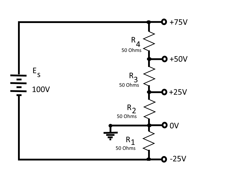
In many cases the load for a voltage divider requires both positive and negative voltage, which can be supplied from a single source voltage by connecting the ground (reference point) between two of the divider resistors. The exact point in the circuit at which the reference point is placed depends upon the voltages required by the loads.
 |
Helpful Definitions
- Direct Current (DC): is an electric current that flows in one direction only.
- Basic Electric Circuit: consists of a source of electrical energy connected to a load. The load uses the energy and changes it to a useful form.
- Schematic Diagram: is a drawn picture of a circuit, which uses symbols to represent components. The space required to depict an electrical or electronic circuit is greatly reduced by the use of a schematic.
- Voltage (E): the electrical force or pressure operating in a circuit.
- Ampere (A): represents the current flow produced by one volt working across one ohm of resistance.
- Resistance (R): the opposition to current. It is measured in ohms (Ω). One ohm of resistance will limit the current produced by one volt to a level of one ampere.
- The Ohm's Formula: can be transposed to find one of the values in a circuit if the other two values are known. You can transpose the Ohm's law formula I = E / R mathematically, or you can use the Ohm's law figure to determine the mathematical relationship between R, E, and I.
- Graphical Analysis: the relationship between R, E, and I can be studied by plotting these quantities on a graph. Such a graph is useful for observing the characteristics of an electrical device.
- Power: is the rate of doing work per unit of time. The time required to perform a given amount of work will determine the power expended. as a formula, P = E * I, where P equals power in watts, E equals voltage in volts, and I equals current in amperes.
- Four Basic Electrical Quantities: are P, I, E, R. Any single unknown quantity can be expressed in terms of any two of the other known quantities. The formula wheel is a simple representation of these relationships.
- Power Rating: in watts indicates the rate at which a device converts electrical energy into another form of energy. The power rating of a resistor indicates the maximum power the resistor can withstand without being destroyed.
- Power Used: by an electrical device is measured in watt-hours. One watt-hour is equal to one watt used continuously for one hour.
- The Efficiency: of an electrical device is equal to the electrical power converted into useful energy divided by the electrical power supplied to the device.
- Horsepower: is a unit of measurement often used to rate electrical motors. It is a unit of work One horsepower is equal to 746 watts.
- Series Circuit: is defined as a circuit that has only one path for current flow.
- Kirchhoff's Voltage: law states: The algebraic sum of the voltage drops in any closed path in a circuit and the electromotive forces in that path is equal to zero, or Ea + Eb + Ec + ... En = 0
- Voltage Polarities: must be used when applying Kirchhoff's voltage law. The point at which current enters a load (resistor) is considered negative with respect to the point at which current leaves the load.
- Series Aiding Voltages: cause current to flow in the same direction; thus the voltages are added.
- Series Opposing Voltages: tend to force current to flow in opposite directions; thus the equivalent voltage is the difference between the opposing voltages.
- Reference Point: is a chosen point in a circuit to which all other points are compared.
- An Open Circuit: is one in which a break exists in the complete conducting pathway.
- A Short Circuit: is an accidental path of low resistance which passes an abnormally high amount of current.
- Internal Resistance: causes a drop in the terminal voltage of a source as current flows through the source. The decrease in terminal voltage is caused by the voltage drop across the internal resistance. All sources of electromotive force have some form of internal resistance.
- High Efficiency: in a circuit is achieved when the resistance of the load is high with respect to the resistance of the source.
- Power Transfer: in a circuit is highest when the resistance of the load equals the resistance of the source.
- Parallel Circuit: is a circuit having more than one current path connected to a common voltage source.
- A Voltage Divider: is a series circuit in which desired portions of the source voltage may be tapped off for use in equipment. Both negative and positive voltage can be provided to the loads by the proper selection of the reference point (ground).
Final Thoughts
Thank you for reading, I hope you found this blog post educational and helpful in some way.