Understanding Transformers
In this blog post I would like to explain the overall basics of what Transformers are and how they are made and used, as I currently understand them to be.
What Is A Transformer?
A Transformer is a device that transfers electrical energy from one circuit to another by means of electromagnetic Induction. The electrical energy is always transferred without a change in frequency, but may involve changes in magnitudes of voltage and current. Because a transformer works on the principle of electromagnetic induction, it must be used with an input source voltage that varies in amplitude (i.e. AC voltage), because it is the constant changing of magnetic flux within the transformers primary winding induced onto the transformers secondary winding that allows a transformer to convert and transform the source voltage and current values on the transformers primary winding into different values onto the transformers secondary winding.
When Alternating Current is applied to a transformer, the voltage and current levels can be increased or decreased by the transformer, depending on if it is a Step-Up transformer or a Step-Down transformer (defined below).
The amount of power used by the load of an electrical circuit is equal to the current in the load times the voltage across the load, or P = EI.
If, for example, the load in an electrical circuit requires an input of 2 amperes at 10 volts (i.e. 20 watts) and the source is capable of delivering only 1 ampere at 20 volts, the circuit could not normally be used with this particular source. However, if a transformer is connected between the source and the load, the voltage can be decreased (stepped down) to 10 volts and the current increased (stepped up) to 2 amperes. Notice that the power (i.e. Watts) remains the same. That is, 20 volts times 1 ampere equals the same power as 10 volts times 2 amperes.
Basic Operation Of A Transformer
In its most basic form a transformer consists of:
- A primary coil or winding.
- A secondary coil or winding.
- A core that supports the coils or windings.
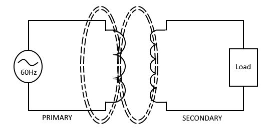
Lets assume that we connect the primary windings to a 60 hertz A.C. voltage source. As a result of the A.C. frequency of 60 hertz, the magnetic field (flux) builds up (expands) and collapses (contracts) about the primary winding 60 times per second. The expanding and contracting magnetic field around the primary winding cuts the secondary winding and induces an alternating voltage into the secondary winding, which then powers the load. This voltage induced onto the secondary winding causes alternating current to flow through the load. The voltage may be stepped up or down depending on the design of both the primary and secondary windings.
Components Of A Transformer
A transformer is basically two coils of wire (called windings) which are wound on some type of core material. In some cases the coils of wire are wound on a cylindrical or rectangular cardboard form. In effect, in this situation, the core material is air and therefore the transformer is called an Air-Core Transformer. Transformers used at low frequencies, such as from 1 to 400 hertz, require a core of low-reluctance magnetic material, usually iron. This type of transformer is called an Iron-Core Transformer. Most power transformers are of the iron-core type.
The principle parts of a transformer and their primary functions are:
- The CORE, which provides a path for the magnetic lines of flux.
- The PRIMARY WINDING, which receives energy from the A.C. power source.
- The SECONDARY WINDING, which receives energy from the primary winding and delivers it to the load.
- The ENCLOSURE, which protects the above components from dirt, moisture, environmental and mechanical damages.
The Core
The composition of a transformer core depends on such factors as voltage, current, and frequency. Size limitations and construction costs are also factors to be considered.
Commonly used core materials are air, soft iron, and steel. Each of these materials have suitabilities for particular applications while at the same time being unsuitable for other applications. Generally, air-core transformers are used when the voltage source has a high frequency (above 20 kHz). Iron-core transformers are usually used when the source frequency is low (below 20 kHz). Soft-iron-core transformers are very useful when the application requires the transformer to be physically small, yet effective. The iron-core transformer provides better power transfer than does the air-core transformer. A transformer whose core is constructed of laminated sheets of steel dissipates heat readily, therefore it provides efficient transfer of power.
Steel laminations are insulated with a nonconducting material, such as varnish, and then formed into a core. It takes about 50 such laminations to make a core an inch thick. The purpose of the laminations is to reduce certain losses.
The most efficient transformer core is one that offers the best path for the most lines of flux with the least loss in magnetic and electrical energy.
There are two main shapes of cores used in laminated-steel-core transformers. One is the Hollow-Core, so named because the core is shaped with a hollow square through the center. The transformer windings are wrapped around both sides of the core. The most popular and efficient transformer core is the Shell Core. Each layer of the core consists of E-shaped and I-shaped sections of metal. These sections are butted together to form the laminations. The laminations are insulated from each other and then pressed together to form the core.
Transformer Windings
The transformer consists of two coils called Windings, which are wrapped around a core. The transformer operates when a source of A.C. voltage is connected to one of the windings and a load device is connected to the other. The winding that is connected to the A.C. voltage source is called the Primary Winding. The winding that is connected to the load is called the Secondary Winding.
With the shell-type transformer, the primary is wound in layers directly on a rectangular cardboard form. The primary consists of many turns of relatively small wire. The wire is coated with varnish so that each turn of the winding is insulated from every other turn. In a transformer designed for high-voltage applications, sheets of insulating material, such as paper, are placed between the layers of windings to provide additional insulation.
When the primary winding is completely wound, it is wrapped in insulating paper or cloth. The secondary winding is then wound on top of the primary winding. After the secondary winding is complete, it too is covered with insulating paper. Next, the E and I sections of the iron core are inserted into and around the windings.
The leads from the windings are normally brought out through a hole in the enclosure of the transformer. Sometimes, terminals may be provided on the enclosure for connections to the windings. These leads are to be connected to the source and load, respectively.
How Transformers Work
A transformer is capable of supplying voltages to a load which are usually higher or lower than the source voltage. This is accomplished through mutual Induction, which takes place when the changing magnetic field produced by the primary winding cuts the secondary winding. As the changing magnetic field cuts the secondary winding, that magnetic field is induced into the coil, producing a counter emf, which results in current to flow through the secondary winding.
No-Load Condition
A no-load condition is said to exist when a voltage is applied to the primary, but no load is connected to the secondary. This may be caused by an on-off switch, a blown fuse, or an open circuit, located in the secondary winding circuit, which removes the load from the secondary winding. The no-load condition exists because there is no current flowing through the secondary winding.
Exciting Current
With the switch open and an A.C. voltage applied to the primary, there is, however, a very small amount of current called Exciting Current flowing in the primary. Essentially, what the exciting current does is Excite the coil of the primary to create a magnetic field. The amount of exciting current is determined by three factors:
- The amount of voltage applied (Ea),
- The resistance (R) of the primary coils wire and core losses, and
- The XL which is dependent on the frequency of the exciting current.
This very small amount of exciting current serves two functions:
- Most of the exciting energy is used to maintain the magnetic field of the primary.
- A small amount of energy is used to overcome the resistance of the wire and core losses which are dissipated in the form of heat (power loss).
Exciting current will flow in the primary winding at all times to maintain this magnetic field, but no transfer of energy will take place as long as the secondary circuit is open.
Producing A Counter EMF
When an alternating current flows through a primary winding, a magnetic field is established around the winding. As the lines of flux expand outward, relative motion is present, and a counter emf is induced in the winding. Flux leaves the primary at the north pole and enters the primary at the south pole. The counter emf induced in the primary has a polarity that opposes the applied voltage, thus opposing the flow of current in the primary. It is the counter emf that limits exciting current to a very low value.
Inducing A Voltage In The Secondary
As the exciting current flows through the primary, magnetic lines o force are generated. During the time current is increasing in the primary, magnetic lines of force expand outward from the primary and cut the secondary. A voltage is induced into a coil when magnetic lines cut across it. Therefore, the voltage across the primary causes a voltage to be induced across the secondary.
Primary And Secondary Phase Relationship
The secondary voltage of a simple transformer may be either in phase or out of phase with the primary voltage. This depends on the direction in which the windings are wound and the arrangement of the connections to the external circuit (load). Simply, this means that the two voltages may rise and fall together or one may rise while the other is falling.
Transformers in which the secondary voltage is in phase with the primary are referred to as Like-Wound transformers, while those in which the voltages are 180 degrees out of phase are called Unlike-Wound transformers.
Dots are used to indicate points on a transformer schematic symbol that have the same instantaneous polarity (points that are in phase). This is important to know because they specify if the transformers primary and secondary coils are in-phase (like-wound) or out-of-phase (unlike-wound), which will affect the voltage polarity at a given moment in time.
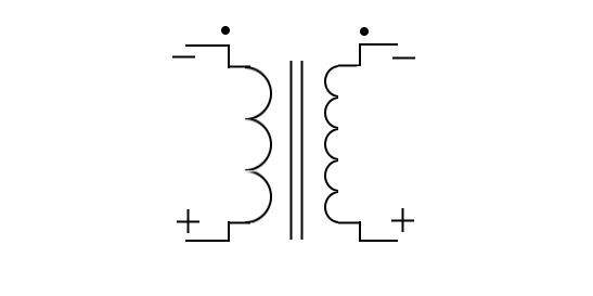
The use of phase-indicating dots is illustrated as follows:
 |
 |
In part (A) of the figure above, both the primary and secondary windings are wound from top to bottom in a clockwise direction. When constructed in this manner, the top lead of the primary and the top lead of the secondary have the Same polarity. This is indicated by the dots on the transformer schematic symbol, as shown above. A lack of phasing dots indicates a reversal of polarity.
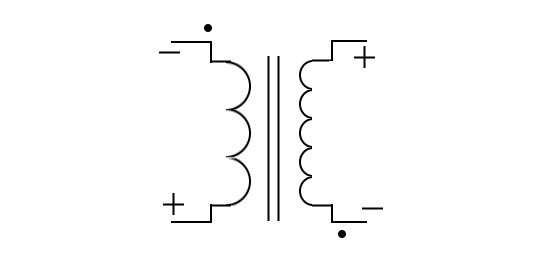
In part (B) of the figure above, the primary is wound in a clockwise direction from top to bottom, while the secondary is wound in a counterclockwise direction. The top leads of the primary and secondary have Opposite polarities. This is indicated by the dots being placed on opposite ends of the transformer symbol. Thus, the polarity of the voltage at the terminals of the secondary of a transformer depends on the direction in which the secondary is wound with respect to the primary.
Coefficient Of Coupling
The Coefficient Of Coupling of a transformer is dependent on the portion of the total flux lines that cuts both primary and secondary windings. Ideally, all of the flux lines generated by the primary should cut the secondary, and all of the lines of the flux generated by the secondary should cut the primary. The coefficient of coupling would then be one (unity), and maximum energy would be transferred from the primary to the secondary. Practical power transformers use high-permeability silicon steel cores and close spacing between the windings to provide a high coefficient of coupling.
Lines of flux generated by one winding which do not link with the other winding are called Leakage Flux. Since leakage flux generated by the primary does not cut the secondary, it cannot induce a voltage into the secondary. The voltage induced into the secondary is therefore less than it would be if the leakage flux did not exist. Since the effect of leakage flux is to lower the voltage induced into the secondary, the effect can be duplicated by assuming an inductor to the connected in series with the primary. This series Leakage Inductance is assumed to drop part of the applied voltage, leaving less voltage across the primary.
Turns and Voltage (E) Ratios
The total voltage induced into the secondary winding of a transformer is determined mainly by the ratio of the number of turns in the primary to the number of turns in the secondary, and by the amount of voltage applied to the primary.
For Like-Wound transformers, such as in part (A) above, if a primary coil consists of ten turns of wire and its secondary consists of one turn of wire, the lines of flux generated by the primary expand and collapse, and will cut both the ten turns of the primary and the single turn of the secondary. If the length of the wire in the secondary is approximately the same as the length of the wire in each turn in the primary, EMF induced into the secondary will be the same as the EMF induced into each turn in the primary. This means that if the voltage applied to the primary winding is 10 volts, the counter emf in the primary is almost 10 volts. Thus, each turn in the primary will have an induced counter emf of approximately one-tenth of the total applied voltage, or one volt, in this ten-primary to one-secondary configuration. Since this ten-primary to one-secondary configuration has only one turn in the secondary, the emf across the secondary is one volt. This means that the voltage in the transformer was stepped down from 10 volts (in the primary) to 1 volt (in the secondary).
If the transformer had ten turns in its primary, and two turns in its secondary (instead of just one), the emf across the secondary would be two volts. Since the flux induces one volt per turn (10 volt source on the primary which consists of 10 turns, therefore 1 volt per turn), the total voltage across the secondary is two volts. The volts per turn are the same for both primary and secondary windings.
Since the counter emf in the primary is equal (or almost equal) to the applied voltage, a proportion may be set up to express the value of the voltage induced in terms of the voltage applied to the primary and the number of turns in each winding. This proportion also shows the relationship between the number of turns in each winding and the voltage across each winding. This proportion is expressed by the equation:
Es / Ep = Ns / Np
Where:
- Es = voltage induced in the secondary
- Ep = voltage applied to the primary
- Ns = number of turns in the secondary
- Np = number of turns in the primary
Notice the equation shows that the ratio of secondary voltage to primary voltage is equal to the ratio of secondary turns to primary turns. Therefore the same equation can be written as:
Ep * Ns = Es * Np
The following formulas are derived from the above equations:
Transposing for Es : Es = (Ep * Ns) / Np
Transposing for Ep : Ep = (Es * Np) / Ns
If any three of the quantities in the above formulas are known, the fourth quantity can be calculated.
To rephrase it into a simpler statement, if the secondary winding has fewer coils than the primary winding, then the voltage induced on the secondary will be less than the primary. As a result, there is less voltage across the secondary than across the primary.
A transformer in which the voltage across the secondary is less than the voltage across the primary is called a STEP-DOWN transformer.
The reverse is true as well, if the secondary winding has more coils than the primary winding, then the voltage induced on the secondary will be greater than the primary. As a result, there is more voltage across the secondary than across the primary.
A transformer in which the voltage across the secondary is greater than the voltage across the primary is called a STEP-UP transformer.
The ratio of a one-primary to four-secondary step-up transformer should be written as 1:4, with the primary always listed first and the secondary always listed last.
Effect Of A Load
When a load device is connected across the secondary winding of a transformer, current flows through the secondary and the load. The magnetic field produced by the current in the secondary interacts with the magnetic field produced by the current in the primary. This interaction results from a mutual inductance between the primary and secondary winding.
Mutual Flux
The total flux in the core of the transformer is common to both the primary and secondary windings. It is also the means by which energy is transferred from the primary winding to the secondary winding. Since this flux links both windings, it is called Mutual Flux. The inductance which produces this flux is also common to both windings and is called mutual inductance.
When a load resistance is connected to the secondary winding, the voltage induced into the secondary winding causes current to flow in the secondary winding. This current produces a flux field about the secondary which is in opposition to the flux field about the primary (Lenz's law). Thus, the flux about the secondary cancels some of the flux about the primary. With less flux surrounding the primary, the counter emf is reduced and more current is drawn from the source. The additional current in the primary generates more lines of flux, nearly reestablishing the original number of total flux lines.
Turns and Current (I) Ratios
The number of flux lines developed in a core is proportional to the magnetizing force (in ampere-turns) of the primary and secondary windings. The ampere-turn (1 * N) is a measure of magnetomotive force; it is defined as the magnetomotive force developed by one ampere of current flowing in a coil of one turn. The flux which exists in the core of a transformer surrounds both the primary and secondary windings. Since the flux is the same for both windings, the ampere-turns in both the primary and secondary windings must be the same.
Therefore:
Ip * Np = Is * Ns
Where:
- Ip * Np = ampere-turns in the primary winding
- Is * Ns = ampere-turns in the secondary winding
By dividing both sides of the equation by Ip * Ns, you obtain:
Np / Ns = Is / Ip
Since : Es / Ep = Ns / Np
Then : Ep / Es = Np / Ns
And : Ep / Es = Is / Ip
Where:
- Ep = voltage applied to the primary in volts
- Es = voltage across the secondary in volts
- Ip = current in the primary in amperes
- Is = current in the secondary in amperes
Notice the equations show the current ratio to be the inverse of the turns ratio and the voltage ratio. This means, a transformer having less turns in the secondary than in the primary would step down the voltage, but would step up the current.
Whenever a transformer steps voltage down then the current is stepped up by the same reverse ratio. The reverse is true also, so whenever a transformer steps voltage up then the current is stepped down.
For example, say we have a 1:5 step-up transformer (which has five times the number of coils in its secondary than it has in its primary), and this transformer is connected to a 10 volt at 1 ampere A.C. power supply. The primary would have 10 volts at 1 ampere. This transformer would step the voltage up by a factor of 5, resulting in 50 volts to now be on the secondary, while at the same time stepping the amperes down by a factor of 5, resulting in 1/5 ampere to now be on the secondary.
If we were to have used a 5:1 step-down transformer (which has five times the number of coils in its primary than it has in its secondary), and this transformer is also connected to a 10 volt at 1 ampere A.C. power supply. The primary would have 10 volts at 1 ampere. This transformer would step the voltage down by a factor of 5, resulting in 2 volts to now be on the secondary, while at the same time stepping the amperes up by a factor of 5, resulting in 5 amperes to now be on the secondary.
Effect On Power
Power (in Watts) is calculated as Voltage times Current. Therefore it can be easily determined that under ideal conditions the total amount of power (in watts) does not change in a transformer, because as the voltage is stepped down the current is stepped up by the same factorial amount, and as the voltage is stepped up the current is stepped down by the same factorial amount.
Aside from results caused by physical damages within the transformer itself, small amounts of power loss may also be naturally experienced due to Copper loss, Eddy-Current loss, Heat loss, and Hysteresis, in addition to other design factors resulting in poor transformer Coefficient Of Coupling ratings.
Transformer Efficiency
The amplitude of the voltage induced in the secondary is depended upon the efficiency of the transformer and the turns ratio. The efficiency of a transformer is related to the power losses in the windings and core of the transformer.
Efficiency (in percentage) equals: (Pout/Pin) * 100
A perfect transformer would have an efficiency of 1.0, or 100%, although in reality it is actually anywhere between 80% to 90% in small power transformers, and as high as 99% in large expensive commercial powerline transformers.
To compute the efficiency of a transformer, the input power to and the output power from the transformer must be known. The input power is equal to the product of the voltage applied to the primary and the current in the primary. The output power is equal to the poroduct of the voltage across the secondary and the current in the secondary. The difference between the input power and the output power represents a power loss.
The percentage of efficiency of a transformer can be calculated by using the standard efficiency formula:
Efficiency (in %) = (Pout/Pin) * 100
Where:
- Pout = total output power delivered to the load
- Pin = total input power
Other Types Of Transformers
- Power Transformer
- A power-transformer is a transformer that has two or more windings wound on a laminated iron core. The power-transformer is used to supply stepped up and stepped down values of voltage to the various circuits in electrical equipment.
- Autotransformer:
- An autotransformer is a special type of transformer, that only has one winding, instead of two. The entire winding can be used as the primary and part of the winding as the secondary, or part of the winding can be used as the primary and the entire winding can be used as the secondary.
- Audio-Frequency Transformer:
- A transformer used in audio-frequency circuits to transfer af signals from one circuit to another.
- Radio-Frequency Transformer:
- A transformer used in radio-frequency circuits to transfer rf signals from one circuit to another.
- Impedance-Matching Transformer:
- A transformer used to match the impedance of the source and the impedance of the load, expressed by the equation:
(Np/Ns) = Sqrt(Zp/Zs)
Final Thoughts
Thank you for reading, I hope you found this blog post educational and helpful in some way.